GLIDER Scanner
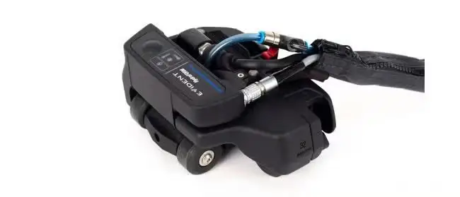
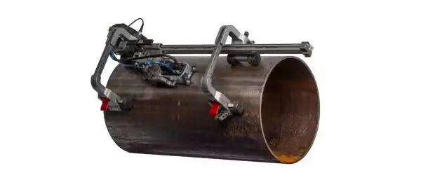
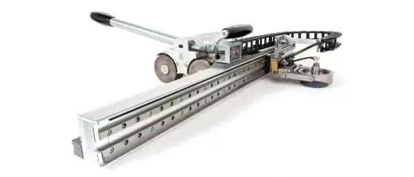
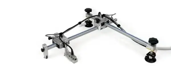
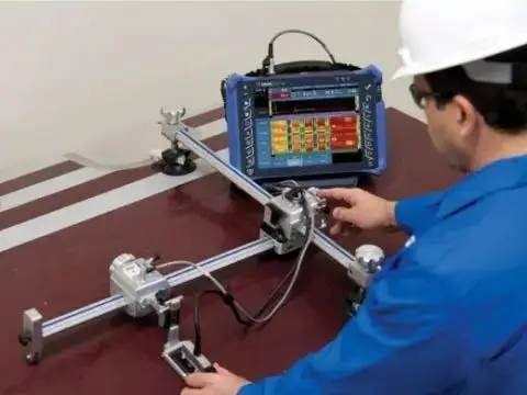
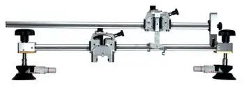
The GLIDER scanner is a 2-axis (X-Y) encoding scanner for the manual inspection of slightly curved or flat composite surfaces. The scanner, held by suction cups is well suited for raster scanning.…
- Conventional ultrasonics (UT)
- Phased array ultrasonics (PAUT)
- Eddy current (EC)
- Eddy current array (ECA)
Manual X-Y Scanner
The GLIDER X-Y Scanner is a 2-axis encoding scanner for the manual inspection of slightly curved or flat composite surfaces. The scanner is well suited for raster scanning with the following technologies:
- Conventional ultrasonics (UT)
- Phased array ultrasonics (PAUT)
- Eddy current (EC)
- Eddy current array (ECA)
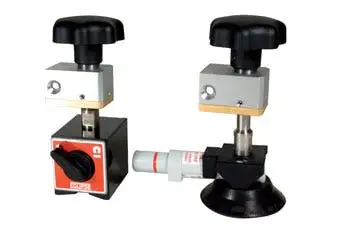
Commonly inspected materials include composites and aluminum, using suction-cup pods; and carbon steel, using optional magnetic pods.
Design Characteristics
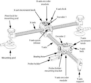
The X-axis is attached to two mounting pods. Depending on the material to inspect, one of the following models can be used:
- Suction-cup mounting pod (included)
- Magnetic mounting pod (optional)
There are two encoder modules (one on each axis) to measure the probe position. The displacement of these modules can be in 3.27 mm steps, free running, or locked.
The scanner comes in three formats (18 in., 24 in., and 36 in.), depending on the scan coverage needed:
- GLIDER 18 x 18
- GLIDER 24 x 24
- GLIDER 36 x 36
Options
Features
- Well suited for phased array UT, conventional UT, and eddy current inspection techniques using one probe
- Two axes with waterproof encoders for position-encoded X-Y scans
- Axis positioning with minimal backlash
- Both modules are mounted on bearings for precise and smooth displacement
- Two pivot-equipped mounting pods enable surface following
- Locking devices allow each axis to be locked
- Module displacement can be in increments of 3.27 mm or in free-running mode
- The probe holder is mounted on a bearing-arm system that can be spring loaded if needed.
- Aluminum frame is used for lightweight and rust-free components
- Sliding Y-axis provides greater scan flexibility and improved portability
Technical Specifications
| Model | X (length)mm (in.) / Y (width)mm (in.) / Z (height)mm (in.) |
|---|---|
| GLIDER 18×18 | 700 (28) / 690 (27) / 152 (6) |
| GLIDER 24×24 | 900 (35) / 845 (33) / 152 (6) |
| GLIDER 36×36 | 1200 (47) / 1150 (45) / 152 (6) |
Applications
Inspection scenarios where the GLIDER Scanner is used: